STATE SPACE:
State space is where the system being investigated is represented in the form of matrix equations in the form shown below.
[dx/dt] = [A][x] + [B][u]
[y] = [C][x] + D[u]
where A, B C D are used to represent the linear differential equations between the various system parameters.
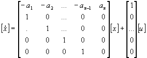
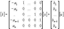
The matrices can have several different forms such as shown below:
Controllable Canonical Form
![]()

![]()
Observable Canonical Form

![]()
State Space representation of the system transfer function:
[dx/dt] = [A][x] + [B][u]
[y] = [C][x] + D[u]
Given the system above the transfer function G(s) is given by:
G(s) = C(sI - A)-1B + D
EXAMPLE 1:
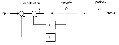
Consider the system shown below:

The two summation junctions can be collated into one junction.
e = input - K*position - B*velocity
define states: x1 & x2 as shown in the diagram and develop state equations:
dx1/dt = x2
dx2/dt = e = input - K*position - B*velocity
Also we have: output = x1, input = u, x1 = position, x2 = velocity
we can express dx2/dt as:
dx2/dt = u - K*x1 - B*x2
Therefore our state equations are:
dx1/dt = x2
dx2/dt = u - K*x1 - B*x2
y = x1
In matrix form the above equations are:
![]()
A more usual way to express the above is to use the dot notation shown below:
![]()
![]()
EXAMPLE 2:
Represent the transfer function shown below in state space form:
Y(s) / U(s) = (2s + 3) / (s2 + 5s + 6)
Using Partial Fractions we can re-write the above equation as:
Y(s) / U(s) = 3 / (s + 3) - 1 / (s + 2)
define state x1 & x2 as:
x1 = U(s) *3 / (s + 3)
x2 = - U(s) *1 / (s + 2)
re arrange equations to:
x1* (s + 3) = U(s) *3
dx1/dt + 3x1 = U(s) *3
x2*(s + 2) = -U(s) *1
dx2/dt + 2x2 = -U(s) *1
dx1/dt = - 3x1 + U(s) *3
dx2/dt = - 2x2 - U(s) *1
the above equations are of the required form [dx/dt] = [A][x] + [B][u]
from the time domain we see that
y(t) = x1(t) + x2(t) in state space form this corresponds to the equation shown below:
[y] = [1 1][x]